¶ IronOX AMR
¶ Contents
- Robot Anatomy: Components and Connections
- Network Configuration and Remote Access
- Starting the AMR
- Teleoperation Setup
- Safety PLC Connection and E-Stop Logic Modification
- Connecting to the ELMO Motor Driver
- Software Architecture Overview
- Autonomous Navigation Setup
- RVIZ Visualization Setup
- Debugging: Important Topics and Commands
- Sound Configuration
¶ 1. Robot Anatomy: Components and Connections
¶ 1.1 Components Inside the Robot:
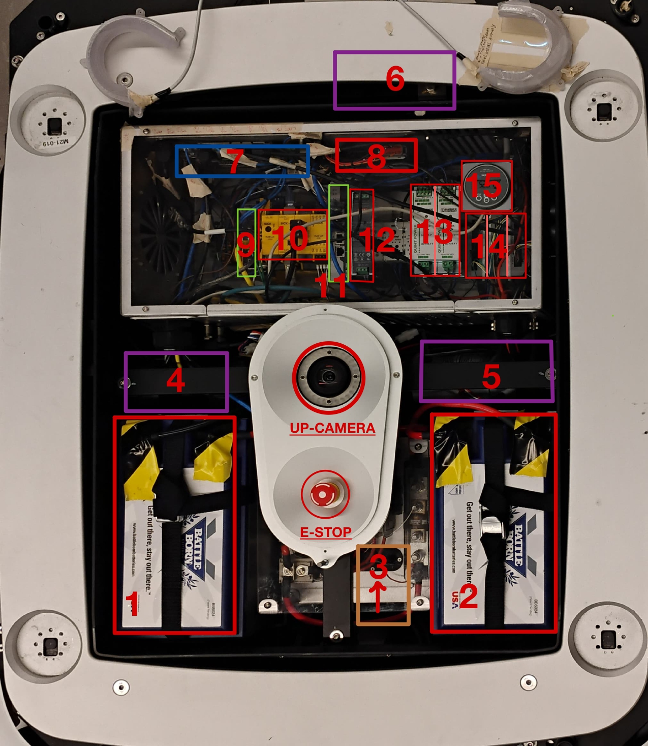
| Number | Component Name | Description |
|---|---|---|
| 1, 2 | 24V LiFe Battery | Both batteries are connected in series for 48V power source Link |
| 3 | Connection Plate | Act as a ground(-ve) for power distribution. All the MCBs and Fuse are here |
| 4,5 | BLDC Wheel Motors | Wheel motors, attached to robot diff drive wheels. |
| 6 | BLDC Lifter Motor | Motor for the lifter |
| 7 | Onboard PC | 7th Gen Core™ i7 processor running Ubuntu 20.04 Link |
| 8 | Radio | Radio receiver for emergency stop |
| 9 | LAN Switch | Switch to connect PLC Onboard PC |
| 10 | Safety PLC | It's SICK FX3-CPU for safety system Link |
| 11 | LAN Switch | Switch to connect PLC and Lidars |
| 12 | DC-DC 48V-48V converter | MeanWell's DDR 120C-48 dc to dc converter. Maybe used as isolator. Link |
| 13 | Two DC-DC 48V-24V converter | Phoenix Contact 48V to 24V, 5 amp DC-DC converter Link |
| 14 | Three Motor Controllers | Elmo Motor controllers for each motors (left, right wheel and lifter) Link |
| 15 | Battery Indicator | Connected to Battrey BMS. (Ideally it should be outside) |
| 16 | SICK LiDAR | Connected to Safety PLC via ethernet and sharing the network with the Onboard PC. Range 10m Link |
¶ 1.2 Power Box Interface:
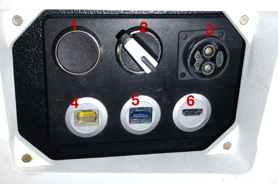
| Number | Component Name | Description |
|---|---|---|
| 1 | Reset Button | Push button to release Motor Contractor |
| 2 | Power ON/OFF Switch | Toggle to turn on the robot |
| 3 | Charging Port | Plug charger male end here |
| 4 | LAN Port | Connects with the robot's internal network |
| 5 | USB port | Connects to the onboard PC |
| 6 | Hdmi port | Connects to the onboard PC |
¶ 1.3 Sensor Configuration:
- LiDARs: 3 units (Front, Rear Left, Rear Right)
- Cameras: 1 upward-facing unit, additional front-facing units (not visible in images)
- LED Indicators: Front and rear LED strips for status indication
- Emergency Controls: Centrally located E-STOP button
- Power System: Battery and charging connections.
- Motors: Linked via the ELMO motor driver.
- Sensors: Includes LIDAR, cameras, and IMUs with labeled ports.
- Main Controller: Connections for the onboard computer.
¶ 1.4 Connection Overview:
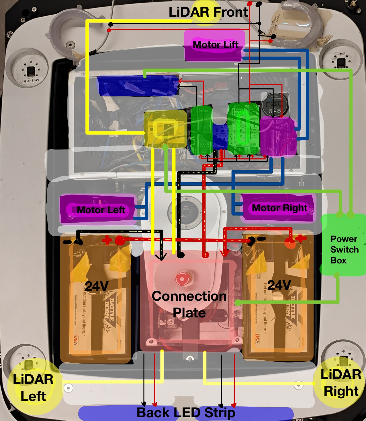
¶ Figure 1.4: Major component's connection Overview
¶ 2. Network Configuration and Remote Access
¶ Network Information
The IronOX AMR uses a dedicated network configuration for its components. Below are the login credentials and IP addresses for all system components:
¶ Login Credentials
- Username:
iron - Password:
iron
¶ Component IP Addresses
| Component | IP Address |
|---|---|
| Onboard PC | 10.20.20.42 |
| Safety PLC | 10.20.20.204 |
| Rear Left Lidar | 10.20.20.203 |
| Rear Right Lidar | 10.20.20.202 |
| Front Lidar | 10.20.20.201 |
¶ SSH Setup
Follow these steps to establish a secure connection to the IronOX AMR:
-
Network Configuration:
- Connect your laptop to the same network as the robot
- Configure a compatible static IP (recommended:
10.20.20.100) - Set subnet mask to
255.255.255.0
-
Simple Connection Setup:
- Connect with robot vis SSH:
ssh iron@10.20.20.42 -XC -
Quick Connection Setup (Optional):
- Install sshpass utility if not already present:
$ sudo apt-get install sshpass - Add this convenient alias to your
~/.bashrcfile:$ echo 'alias ironox="sshpass -p iron ssh iron@10.20.20.42"' >> ~/.bashrc $ source ~/.bashrc - Connect with a single command:
$ ironox
- Install sshpass utility if not already present:
-
Connection Troubleshooting:
- If unable to connect, verify:
- Robot power status is ON
- Your network configuration matches requirements
- Network connectivity with ping:
$ ping 10.20.20.42
- If unable to connect, verify:
¶ RVIZ Visualization
The robot's software stack runs in Docker containers on the onboard PC. To visualize ROS topics on your host system using RVIZ, you need to configure a ROS multi-machine setup that allows your local system to connect to the robot's ROS master.
¶ Prerequisites
- Host system connected to the robot's network (IP:
10.20.20.100) - Docker installed on your host system
- Basic understanding of ROS networking concepts
¶ Step 1: Docker Environment Setup
- For First time setup
Set up a ROS Noetic environment using Docker to ensure compatibility:
# Pull the ROS Noetic Docker image
docker pull althack/ros:noetic-gazebo-2025-05-01

# Allow Docker container to access X11 display
xhost +local:docker

# Create and run the container with network access
docker run -it --net=host --privileged --name iron_rviz \
    -e DISPLAY=$DISPLAY -v /tmp/.X11-unix:/tmp/.X11-unix:rw \
    althack/ros:noetic-gazebo-2025-05-01 bash
- If you ahve already environment setup:
- Start the container (only one time)
docker start	iron_rviz
xhost +
- Open the container
docker exec -it iron_rviz bash
¶ Step 2: ROS Multi-Machine Configuration
Configure your host system to communicate with the robot's ROS master:
-
Environment Variables Setup:
Inside the Docker container, configure ROS networking:echo "source /opt/ros/noetic/setup.bash" >> ~/.bashrc echo "export ROS_MASTER_URI=http://10.20.20.42:11311" >> ~/.bashrc echo "export ROS_IP=10.20.20.100" >> ~/.bashrc source ~/.bashrc -
Host Resolution Setup:
Configure hostname resolution for better connectivity:# Edit the hosts file sudo vim /etc/hosts # Add the following line: 10.20.20.42 m21-019
¶ Step 3: Connection Verification
Before launching RVIZ, verify that the ROS connection is working properly:
-
Test Topic Visibility:
# This should list all available topics from the robot rostopic list -
Verify Data Flow:
# Check if odometry data is being received rostopic hz /diff_drive_controller/odom # Display a single odometry message rostopic echo -n1 /diff_drive_controller/odom -
Test Additional Topics:
# Check other common robot topics
rostopic hz /scan
rostopic hz /tf
¶ Step 4: Launch RVIZ
Once the connection is verified, you can launch RVIZ for visualization:
-
Start RVIZ:
# Launch RVIZ with GUI support rviz -
Basic RVIZ Configuration:
- Set Fixed Frame to
base_link,odom, ormap(depending on your robot's frame setup) - Add visualization plugins for:
- LaserScan - Visualize lidar data from
/scan - TF - Display coordinate frame transformations
- Map - Show occupancy grid if SLAM is running
- LaserScan - Visualize lidar data from
- Set Fixed Frame to
¶ Troubleshooting Common Issues
Connection Problems:
- Ensure both systems are on the same network subnet
- Verify firewall settings are not blocking ROS communication ports
- Check that the robot's ROS master is running:
rostopic liston the robot
RVIZ Display Issues:
- Run
xhost +local:dockeron the host system before starting the container - Check if
$DISPLAYenvironment variable matches between host and container:
If they don't match, manually set the DISPLAY variable in the container:# On host system echo $DISPLAY # Inside Docker container echo $DISPLAYexport DISPLAY=:0.0 # or whatever your host DISPLAY shows - Verify that the Docker container has proper X11 forwarding enabled
- Check that the correct ROS topics are being published by the robot
- Ensure proper frame transformations are available via
/tf
Performance Issues:
- Reduce the update rate of high-frequency topics in RVIZ
- Consider using
rostopic hzto monitor actual publishing rates - Adjust RVIZ display settings to reduce computational load
¶ Additional Tips
- Save your RVIZ configuration file (
.rviz) for future use - Consider creating a launch file to automatically start RVIZ with the correct configuration
- Monitor network bandwidth usage when visualizing high-data topics like point clouds or images
¶ 3. Starting the AMR
¶ Steps to Start
-
Connections:
- Remove Teleop USB (Don't connect it)
- Connect LAN for SSH
-
Power On:
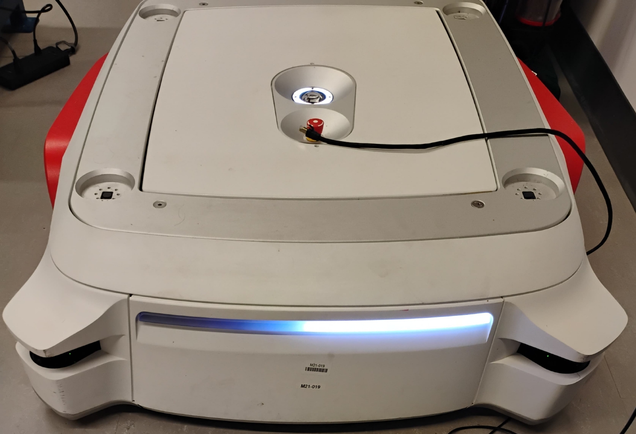
- Locate and toggle the power switch on the robot (refer to Section 1.2: Power Box Interface),you will hear an intial beep sound.
- The power switch is located on the right panel of the robot, near the charging port.
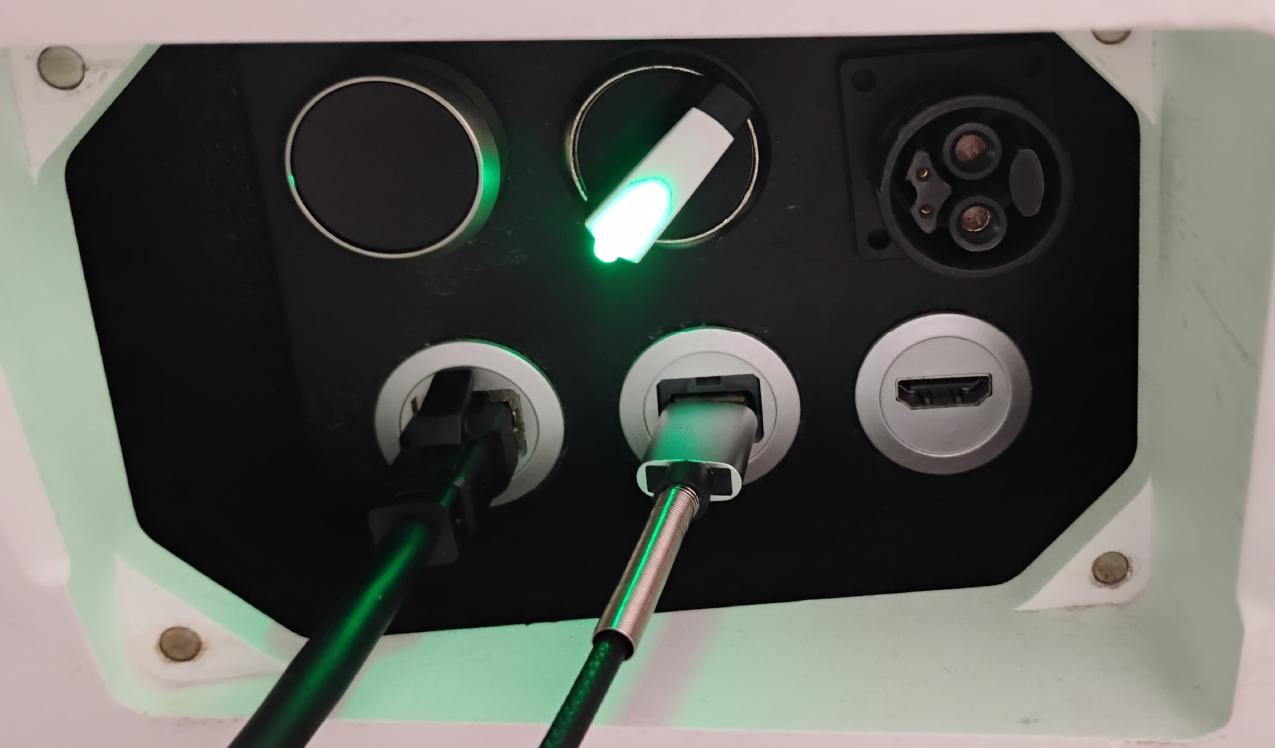
Figure 3.1: Power box after startup- Verify that the fans turn on, power switch light(see Figure 3.1) and indicator lights illuminate (see Figure 3.2).
- You should hear the fans running, which confirms initial power-up.
Figure 3.2: Indicator lights when powered on -
Wait for System Initialization:
- Allow the system to complete its boot sequence.
- The successful initialization is indicated by a beep sound.
- This typically takes approximately 40-50 seconds.
-
Release E-Stop:
- Release the E-stop button if it has been pressed.
-
Reset Safety Circuit:
- Press the reset button (Button1) to release the safety contactor (refer to Section 1.2: Power Box Interface for location).
- Listen for a distinct click sound, which confirms the contactor has been released.
- The robot is now ready for operation.
-
Initialize Robot Pose for Localization (Optional):
- Launch RViz (refer to Section 9: RVIZ Visualization Setup)
- Click on the "2D Pose Estimate" button in the top toolbar
- Click on the map at the robot's current position
- Drag in the direction the robot is facing to set orientation
- The robot should now be localized on the map
¶ Troubleshooting
- If no fan sound is heard when toggling the switch, check battery voltage(must be above 49 V) open the top panel.
- If the beep sound doesn't occur after waiting, the system may need to be restarted.
- If no click sound occurs after pressing reset, the safety circuit may require inspection.
¶ 4. Teleoperation Setup
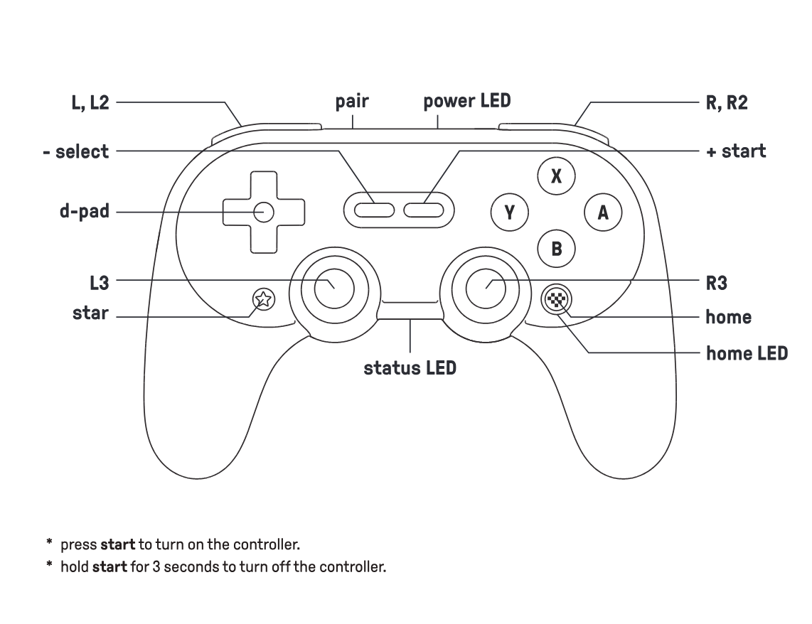
¶ Controller Overview
The IronOX AMR comes with an 8BitDo SN30_Pro+ joystick controller controller for manual operation. Any Xbox-compatible controller will also work as the system uses the JOY ROS Pkg to interpret controller data in the sensor_msgs/Joy.
¶ Controller Setup Process
| Steps | Action | Details | Reference Image |
|---|---|---|---|
| 1. | Check Connection Status | Verify the leftmost LED is illuminated green, indicating proper connection. Remove the USB and plug it back again if its not connected. | 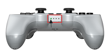 |
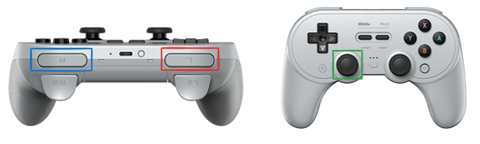
| 2. | Activate Controller | If the Home LED is not blinking, press L + Star buttons simultaneously. The Home LED should begin blinking to indicate activation |
 |
| 3. | Verify Controller Status | Press the L button and check the Home LED status |
 |
| 4. | Operate the AMR | Control movement with the L3 joystick while holding the L button. For increased speed, use L+R buttons simultaneously |
 |
¶ Control Commands
- Basic Movement: Hold
L button+ moveL3 joystick - High-Speed Mode: Hold
L+R buttons+ moveL3 joystick - Emergency Stop: Release all buttons
¶ Troubleshooting Guide
If the robot doesn't respond to controller commands after following the setup process, check these common issues:
-
Contactor Status
- Verify the contactor is engaged
- Press the
Resetbutton once more to ensure system initialization
-
Controller Communication
- If contactor is on but no response, the serial connection may be compromised
- Verification steps:
- SSH into the IronOX system (see Section 2)
- Access the test container (see Section 10)
- Monitor the
/joytopic rate while pressing controller buttons:rostopic hz /joy - If no data appears, restart the hardware container:
docker restart ros_workspace_hardware_1
-
Battery Level
- Low battery can cause intermittent controller response
- Open the top panel to check battery indicator on the BMS display panel
-
Reboot System
- If nothings works, its always better to restart the robot one more time. Make sure you have taken out the teleop USB cabel.
¶ 5. Safety PLC Connection and E-Stop Logic Modification
¶ 5.1 Required Software
The SICK FX3-CPU safety PLC requires the official SICK Safety Designer software:
- SICK Safety Designer:
- Official configuration software for SICK FX3 safety controllers
- Current version: Safety Designer Engineering Tool
- Download from SICK's official website
- Version tested on: Version 2024.02
- System Requirements:
- Windows 10, Version 22H2 (64 bit) or Windows 11, Version 23H2
- X64-based processor
- 2GHz processor or better
- 1GB available disk space
- Additional software Microsoft .Net Framework 4.7.2 is a prerequisite
¶ 5.2 Connection Process
¶ Step 1: Launch Safety Designer
- Open the SICK Safety Designer software on your Windows computer
- You'll see the start screen with options to create a new project or open an existing one
- For first-time setup, choose "New project"
- For subsequent connections, you can select "Open project" to load a previously saved configuration
¶ Step 2: Search for Devices
- If starting a new project, click on "Search for devices" button
- The software will scan the network for compatible SICK devices as shown in the figure 5.2 below.
- Ensure your computer is on the same subnet (10.20.20.xxx)
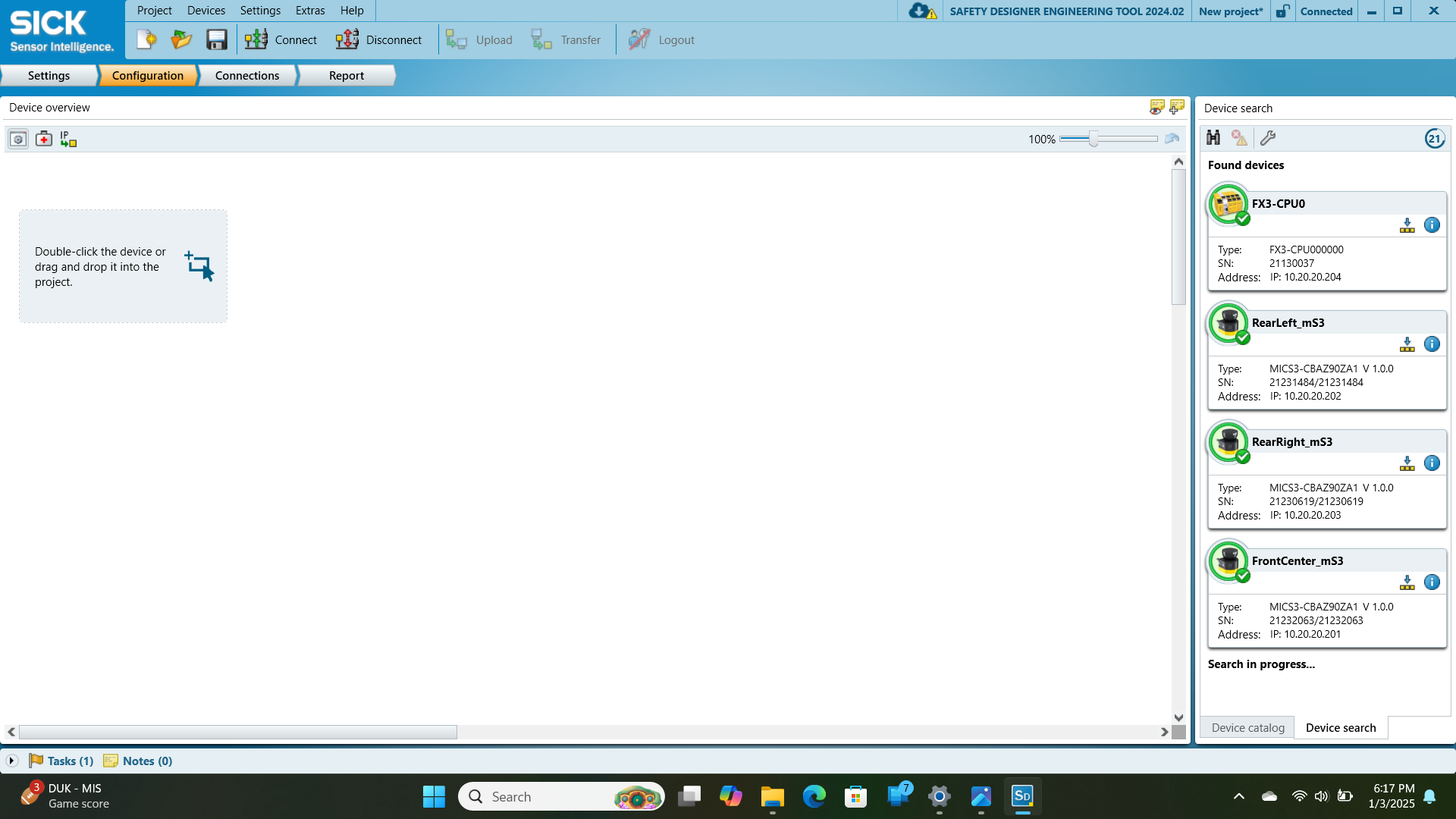
¶ Step 3: Add Devices to Project
- Once devices are found, they will appear in the "Found devices" section
- In the right panel of
Device Searchfigure 5.2, you should see:- FX3-CPU0 (Main PLC controller) at IP: 10.20.20.204
- RearLeft_mS3 (Safety scanner) at IP: 10.20.20.202
- RearRight_mS3 (Safety scanner) at IP: 10.20.20.203
- FrontCenter_mS3 (Safety scanner) at IP: 10.20.20.201
- Double-click each device or drag and drop it into the project area
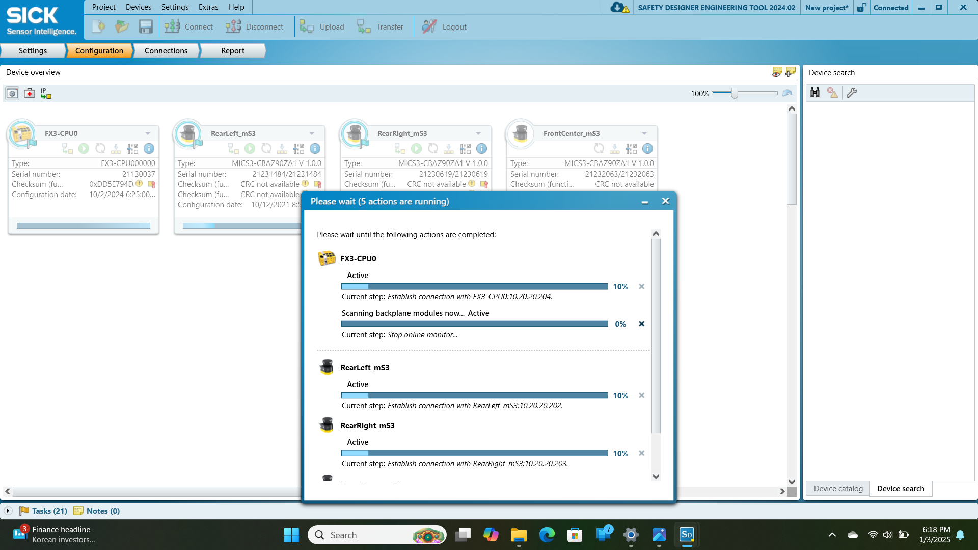
¶ Step 4: Wait for Connection
- The software will establish connections to all devices
- A progress dialog will appear showing "Please wait (x actions are running)" as shown in the figure 5.3 below.
- Connection steps for each device will be shown:
- "Establish connection with FX3-CPU0:10.20.20.204"
- "Establish connection with RearLeft_mS3:10.20.20.202"
- "Establish connection with RearRight_mS3:10.20.20.203"
- "Establish connection with FrontCenter_mS3:10.20.20.201"
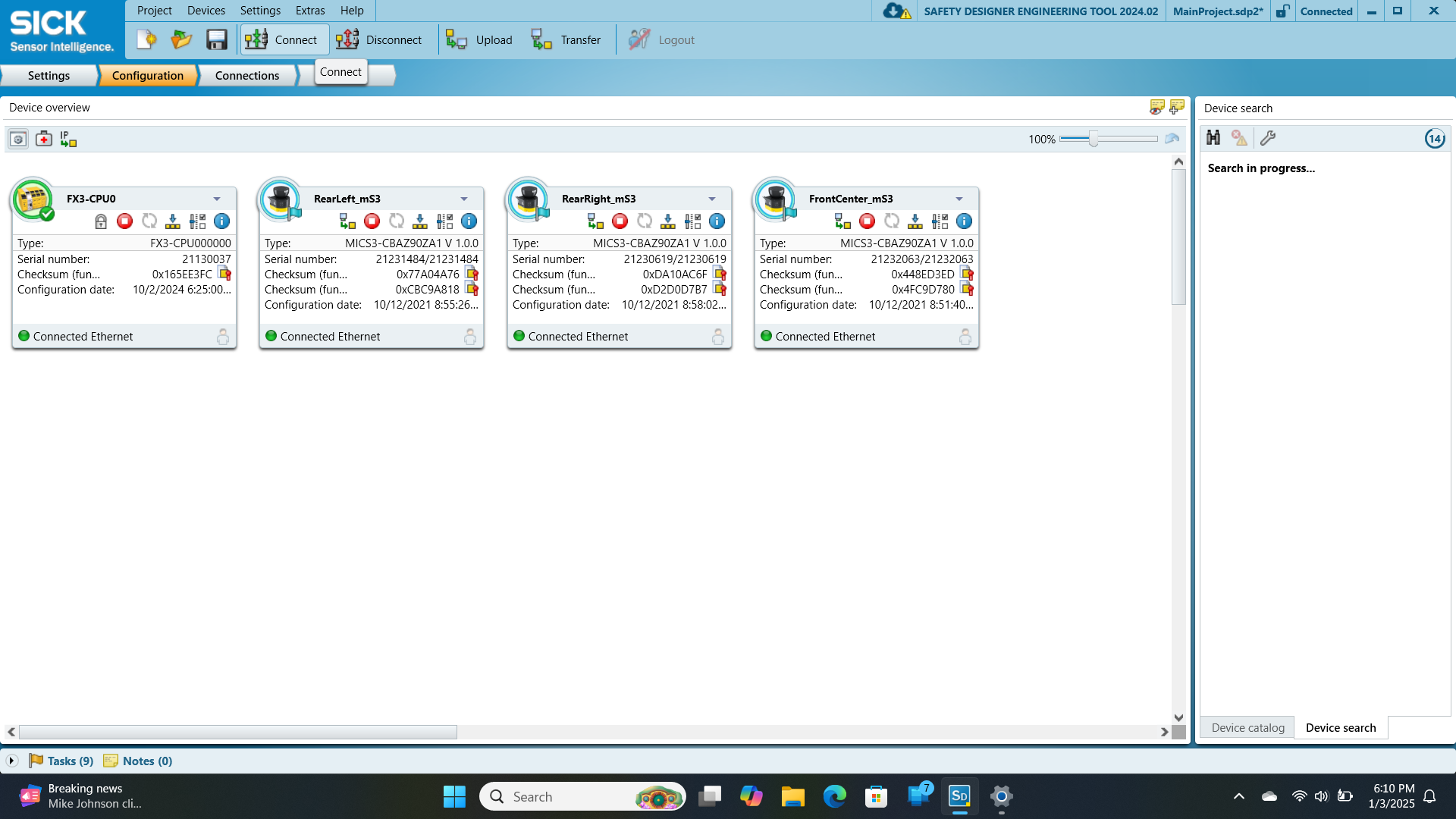
¶ Step 5: Verify Connections
- Once all connections are established, green indicators will appear
- Each device will show "Connected Ethernet" status
- The main interface will display all connected devices with their details as shown in the below image:
- Device type
- Serial number
- IP address
- Safety network number
¶ Step 6: Save Project (Recommended)
- After successful connection, save your project
- Click "Project" → "Save As" and provide a descriptive name
- This allows you to quickly reconnect in the future by selecting "Open project" from the start screen
¶ 5.3 Understanding the System Configuration
The IronOX PLC safety system consists of two main components:
-
FX3-CPU0 (Main Controller):
- Contains all the control-related logic for the system
- Houses the emergency stop logic, restart conditions, and motor control safety
- This is where the programming changes have been made
-
Safety LiDARs (microScan3):
- Three units: FrontCenter_mS3, RearLeft_mS3, and RearRight_mS3
- Each LiDAR has configured safety fields for obstacle detection
- If you need to modify safety field configurations, select the specific LiDAR device
¶ 5.4 CPU Logic Modifications
You can open the CPU logic by double clicking on the FX3-CPU0 icon.
The following changes have been made to the CPU logic to address radio emergency stop issues:
¶ 5.4.1 Emergency Stop System Changes
- Remote E-Stop Signal Bypass in Remote Signals Tab:
- In the "Remote Signals" tab, the connection between "Remote E-Stop.XTIO[2]" and the on-delay timer has been removed.
- This was necessary because the radio was consistently sending high signals to this pin, causing operational issues.
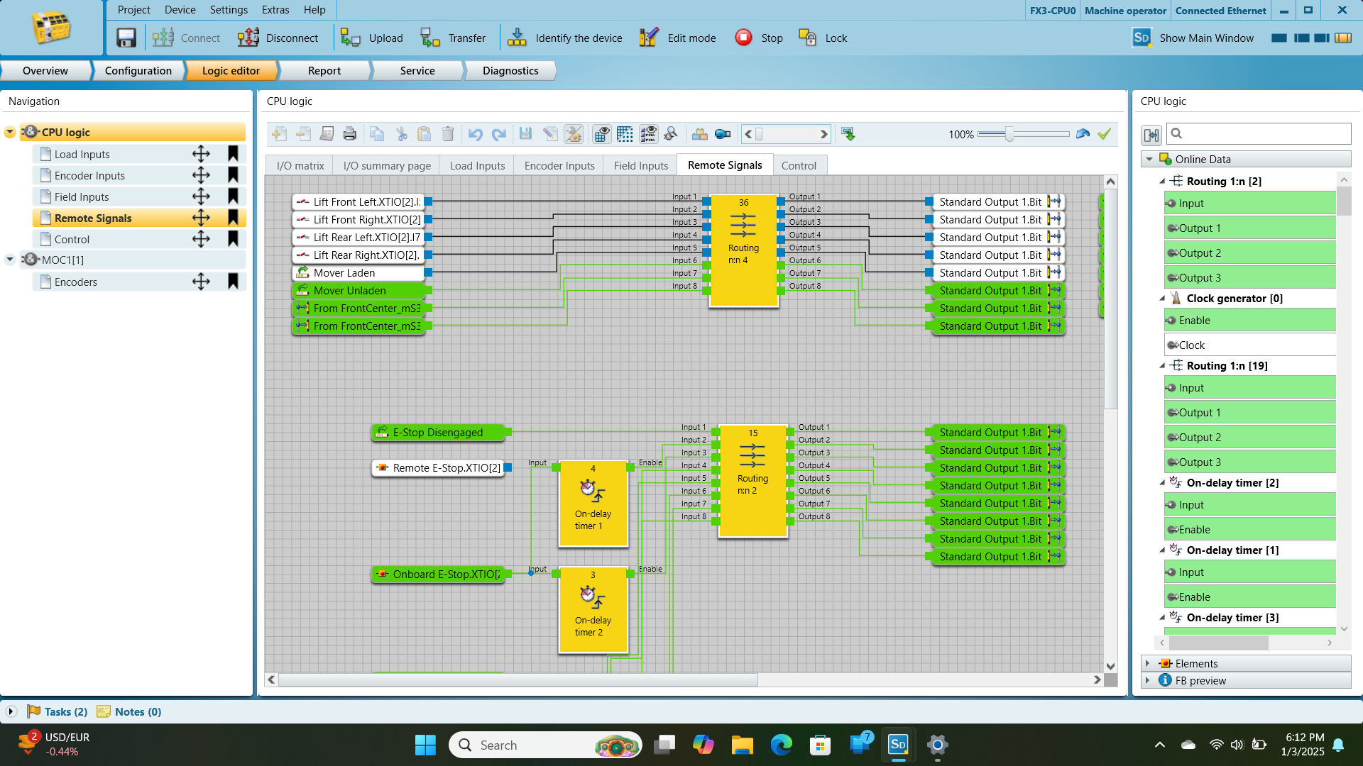
- Restart Logic Modification in Control Tab:
- In the "Control" tab, the connection between "Remote E-Stop.XTIO[2]" and the Restart block has been removed.
- The restart logic now only depends on the "Onboard E-Stop.XTIO[2]" signal.
- The system now only requires the physical onboard E-Stop to be released for restart.
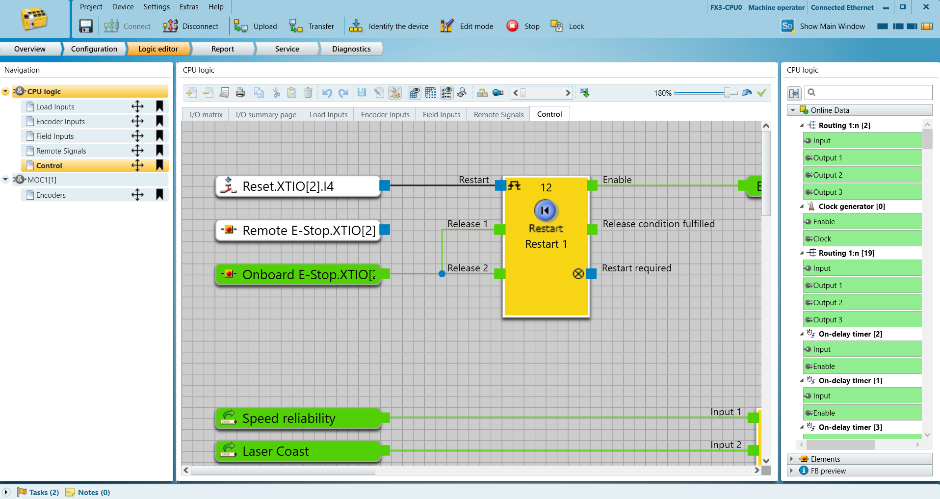
¶ 5.4.2 Other Safety Systems
- The CPU logic still maintains other critical safety features:
- Reset button (Reset.XTIO[2].I4) for manual recovery after emergency stop
- Speed reliability monitoring
- Laser Coast protection
- Physical E-Stop functionality remains fully operational
¶ 5.5 Uploading Configuration Changes
After making modifications to the safety logic, follow these steps to transfer the changes to the PLC:
-
Verify Logic Integrity:
- Check all connections to ensure they are correctly made
- Verify that removal of the Remote E-Stop connections doesn't affect other safety systems
-
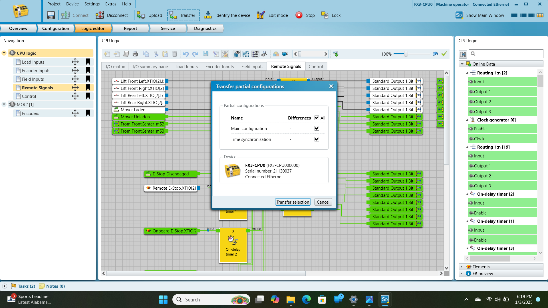
Initiate Transfer:
- Click the "Transfer" button in the toolbar
- Note: "Upload" means transferring data FROM the PLC TO the computer, while "Transfer" means sending data FROM the computer TO the PLC (PLC is the point of reference)
- A dialog showing partial configurations will appear
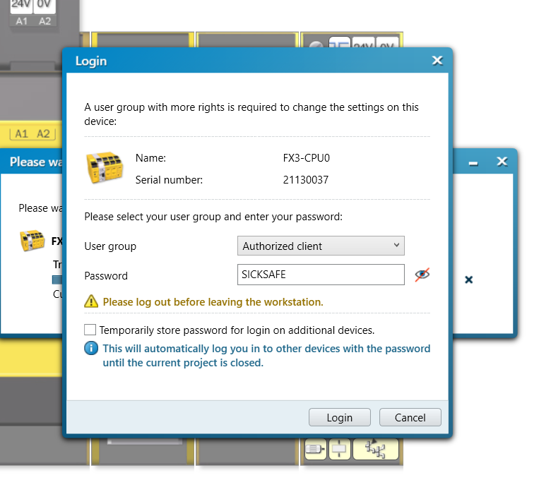
- Authentication:
- You will be prompted to log in with proper credentials
- Select
Authorized clientfrom the dropdown menu - Enter the password:
SICKSAFE - Click
Loginto proceed
-
Complete Transfer:
- Click "Transfer selection" to send the configuration to the PLC
- A progress bar will show the transfer status
- Wait for the transfer to complete successfully
- The system will indicate when the transfer is finished
-
Verification:
- After transfer, verify that the system operates as expected
- Test the physical E-Stop functionality
- Confirm that the system can properly restart after an E-Stop event
-
Future Resolution:
¶ 5.6 Project Backup and Change Documentation
It's critical to create backups of your safety configuration before making any changes. This provides a safe fallback option in case issues arise with new configurations.
¶ Creating a Backup
-
Initial Project Saving:
- After first connecting to the PLC but before making any changes, save the initial project
- Click "Project" → "Save As" and give it a descriptive name like "IronOX_PLC_Original_Configuration"
- Include the date in the filename for version tracking
- This creates a complete backup of the original system state
-
Version Control:
- When making significant changes, save under a new filename
- Use a naming convention like "IronOX_PLC_RadioEStop_Bypass_20250123"
- This maintains a history of changes and configurations
-
Export Configuration:
- For additional backup, use the "Export" function
- Click "Project" → "Export" and save the file to a secure location
- Consider storing backups on a separate device or cloud storage
-
Default Backup:
- A default backup of the original PLC configuration can be downloaded from TODOLink
- This factory default can be used to restore the system to its original state if needed
¶ 6. Connecting to the ELMO Motor Driver(TODO)
¶ Guide
¶ 7. Software Architecture Overview(TODO)
- A block diagram illustrating the layered architecture of the system will be included here.
- Code Filesystem Overview: